 |
| The TV doesn't seem to be doing a good job at rendering videos. Pure colors tend to appear very blocky. The flaw is a little bit odd because it doesn't quite correlate with the chrominance resolution, but is instead more blocky than one would expect from simply incorrect rendering of chrominance. The clip is from a movie called The Black Hole (1979). |
 |
| The same video rendered by VLC in Windows 10 (connected with HDMI). No such annoying blocking is visible. |
 | |
|
 |
| WebOS |
 |
| VLC in Windows 10 (connected with HDMI). |
 |
| The original image used in these tests. ffmpeg -r 24 -f image2 -i image.png -filter_complex loop=799:1 -an vcodec mpeg4 -qscale 1 video.mp4 |
--
Nothing to do with my new TV, but an association developed to the stupid gamma error in most picture scaling software which is nothing much more than due to the fact that pixel brightness (power) is proportional to its value (voltage) squared and most scaling is done on pixel values rather than on pixel brightness. The result is this.


The left image is the original. Middle one is scaled by averaging pixels values.
The right one is scaled by correctly averaging pixel powers.
Sometimes the result of incorrect scaling is significantly distorted colors.
The left image is the original. Middle one scaled by averaging pixels values.
The right one is scaled by averaging pixel powers.


Sometimes the result of incorrect scaling is significantly distorted colors.
The left image is the original. Middle one scaled by averaging pixels values.
The right one is scaled by averaging pixel powers.
RGBA = double(imread('gamma_dalai_lama_gray.jpg')); figure; image(RGBA/255); truesize;
RGBB = double(imread('gamma_colors.jpg')); figure; image(RGBB/255); truesize;
RGB1 = imresize(RGBA, 0.5, 'bicubic')/255;
RGB2 = abs(sqrt(imresize(RGBA.^2, 0.5, 'bicubic')))/255;
RGB3 = imresize(RGBB, 0.5, 'bicubic')/255;
RGB4 = abs(sqrt(imresize(RGBB.^2, 0.5, 'bicubic')))/255;
figure; image(imresize(RGB1, 2, 'nearest')); truesize; imwrite(RGB1, '001.jpg');
figure; image(imresize(RGB2, 2, 'nearest')); truesize; imwrite(RGB2, '002.jpg');
figure; image(imresize(RGB3, 2, 'nearest')); truesize; imwrite(RGB3, '003.jpg');
figure; image(imresize(RGB4, 2, 'nearest')); truesize; imwrite(RGB4, '004.jpg');
--
While we're at it, let's talk about YUV420. This is a signal format used in video compression as human vision is much less sensitive to changes in color than it is to changes in brightness. Instead of recording the primary colors red, green and blue, it records luminance (which is overall brightness of the pixel) with full resolution and chrominance (which records color separate from luminance) with half the original resolution. So for example 4k material recorded in YUV420 as usual has a resolution of 3840x2160 for luminance and a resolution of 1920x1080 for chrominance.
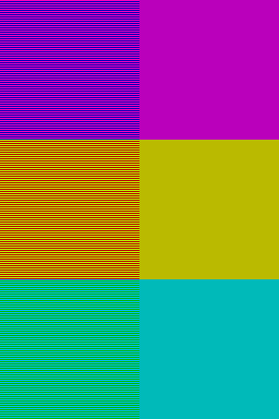
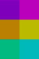
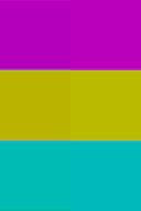
As usual these images can be rendered correctly and incorrectly. Since most display devices are natively RGB these images are eventually always converted back to RGB, but this conversion can be done poorly. A typical mistake is that while rendering the RGB data the chrominance is not interpolated. This results in images where colors are blocky. This is especially apparent in situations where the luminance is the same for both colors, but the colors are different. Below there is an example of how this effect looks like.
 |
| Improperly rendered YUV420 image data. Luminance is rendered properly, but the chrominance data is without interpolation and makes the image look much blockier than with proper interpolation. This effect is visible only in regions with high color saturation and especially in regions where there is no difference in the luminance of the signal, but large differences in the chrominance. |


The original RGB image vs. properly rendered YUV420 where the chrominance signal is interpolated to match the luminance resolution.


RGB = imread('chroma3.png');
YCBCR = rgb2ycbcr(RGB);
YCBCR1 = YCBCR;
YCBCR2 = YCBCR;
N = 2;
YCBCR1(:, :, 2) = imresize(imresize(YCBCR(:, :, 2), 1/N, 'bicubic'), N, 'nearest');
YCBCR1(:, :, 3) = imresize(imresize(YCBCR(:, :, 3), 1/N, 'bicubic'), N, 'nearest');
YCBCR2(:, :, 2) = imresize(imresize(YCBCR(:, :, 2), 1/N, 'bicubic'), N, 'bicubic');
YCBCR2(:, :, 3) = imresize(imresize(YCBCR(:, :, 3), 1/N, 'bicubic'), N, 'bicubic');
RGB2 = ycbcr2rgb(YCBCR1);
RGB3 = ycbcr2rgb(YCBCR2);
--
So let's have a quick look at 30 bit HDR material as well. The compression codec these videos typically use is H.265 also known as HEVC. Pixel format is YUV420p10le where le refers to little endian (signifying order of bit significance). While standard dynamic range is 256 different values given by 8 bpc (8 bits for each of the three colors), the high dynamic range is typically in these videos 1024 different values (10 bpc). The main advantage typically being that more detail can exist in the extremely dark and extremely bright parts of the image.


If you consider the middle image as the standard range of light levels your camera would see, then you can observe that it is missing details both extremely bright and extremely dark or in other words the image is simultaneously overexposed and underexposed. Having additional bits allows one to capture the details in these missing regions. The middle image shows middle 8 bits of the total of 10 and top and bottom show the brightest and darkest 8.
 |
| Suppose your standard dynamic range captures brightness values between the blue bars. Additional bits allow capture of the information outside of your standard range. |
The increased number of bits allows more brightness values which can either be used to increase the dynamic range (more darks and brights) or decrease the minimum distance between different brightness values or some compromise between these two.


Top most picture "simulates" (by exaggerated banding and limited maximum brightness) standard dynamic range with standard number of bits. Limited number of bits results in banding of the brightness values in image which would ideally be continuous change from total darkness to maximum brightness. Middle picture "simulates" a situation with standard dynamic range with two extra bits used to decrease the minimum spacing between brightness values. The third picture "simulates" high dynamic range with two extra bits. One of the bits is used to decrease minimum spacing between brightness values and one to increase the dynamic range now allowing colors brighter than standard dynamic range. This type of high dynamic range still shows more banding than standard dynamic range with two more bits, but less banding than standard dynamic range with standard number of bits. These cases are analogous to SDR8, SDR10 and HDR10.
I'm personally quite capable of seeing the banding in regular SDR8 stripes. Though, I will admit that under normal circumstances when the image contains certain amount of noise, it results in dithering which pretty much masks any banding that might be otherwise visible.


One could also dither in time by making the pixels flicker at suitable duty cycles.
Both of the images above have the same amount of colors.
The lower one is just "dithered" in such a way that spatial pixel noise reflects continuous gradient.
Of course combining some noise improves the result significantly.
close all
clear all
A = 0;
% A = 0.1;
B = 1;
% B = 0.15;
M = 16;
% M = 256;
X = 1200;
Y = 256;
img = zeros(Y, X);
for x = 1:Y
img(x, :) = linspace(A, B, X);
end
figure;
im = round((M-1)*img);
image(uint8(im));
colormap(gray(M));
truesize;
pix = zeros(Y, X);
for y = 1:Y
for x = 1:X
p = (M-1)*img(y, x);
q = floor((M-1)*img(y, x));
if rand>p-q
pix(y, x) = q;
else
pix(y, x) = q + 1;
end
end
end
figure;
image(uint8(pix));
colormap(gray(M));
truesize;
pixx = pix;
pix = zeros(Y, X);
for y = 1:Y
for x = 1:X
p = (M-1)*img(y, x);
q = floor((M-1)*img(y, x));
if rand>p-q
v = q;
else
v = q + 1;
end
m = round(randn/2);
while abs(m)>1
m = round(randn/2);
end
if v>0 && v<M-1
pix(y, x) = v + m;
else
pix(y, x) = v;
end
end
end
figure;
image(uint8(pix));
colormap(gray(M));
truesize;
figure; hold on;
plot(mean(pix, 1));

