Wednesday 5 August 2020

YM3812

I had one old broken Sound Blaster ISA card and decided to pull the music chip from it to see if it worked. This was the Yamaha YM3812 or otherwise known as OPL2. It's the same chip that was used in Adlib cards. Pretty much everyone who played DOS games back in the day knew the sound of this chip.


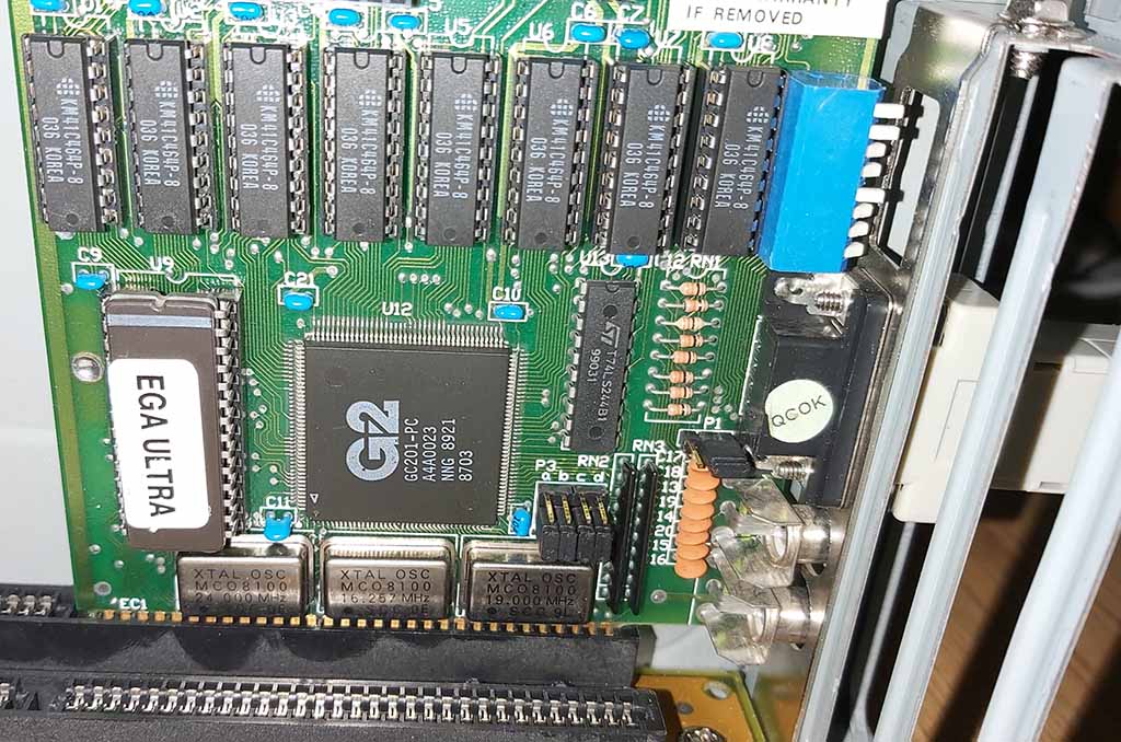
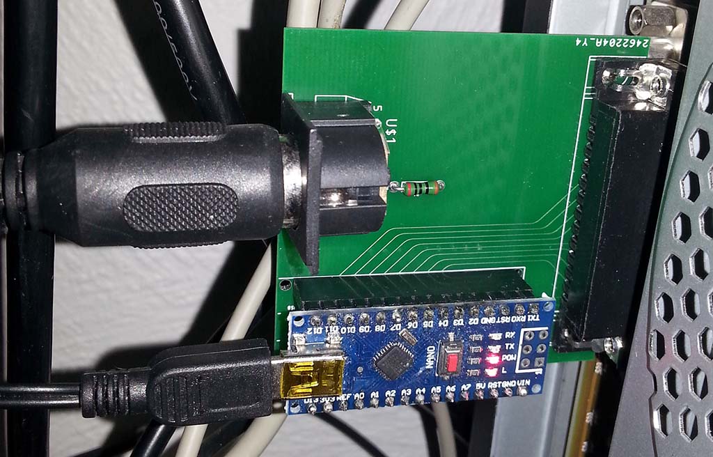
This chip has a rather peculiar sample format, it's 13 bit floating point with 10 bits for mantissa and 3 bits for exponent. The chip requires 3.58 MHz input, uses 8 data bits and one address bit. I used a cheap FPGA board to generate the clock for the chip and fed the digital samples back to the FPGA. I converted the floating point number into regular 16-bit integer and used a software delta-sigma modulator running at 50 MHz to convert back to analog signal.


The chip contrary to the datasheets 16 bits seemed to be output 18 bits during a single SYNC cycle (SYNC is cyan in the above image, CLK is yellow). First 5 extra bits were irrelevant. According to the datasheet only first 3 bits were supposed to be irrelevant. It also appears this chips seemed to work fine with 3.3 V where in the datasheet the minimum voltage was listed as 4.5 V. Operating it with 3.3 V was convenient as my FPGA supplied this voltage and could also only accept 3.3 V logic.


The above is the signal directly measured from the 1-bit digital FPGA pin which is sigma-delta modulated (1st order) digital-to-analog conversion of the signal generated by the YM3812 chip. The sampling frequency is just so high (50 MHz) that it looks very good analog signal when low pass filtered.

Taking a running average (a kind of low pass filter) of the delta-sigma modulated signal yields an analog signal. The higher the "oversampling" rate, the more faithful the filtered signal is to the original (up to some high frequency cutoff).

Second order delta-sigma modulation shapes the noise in order to improve the signal-to-noise ratio even further at the expense of the S/N at the higher frequencies.

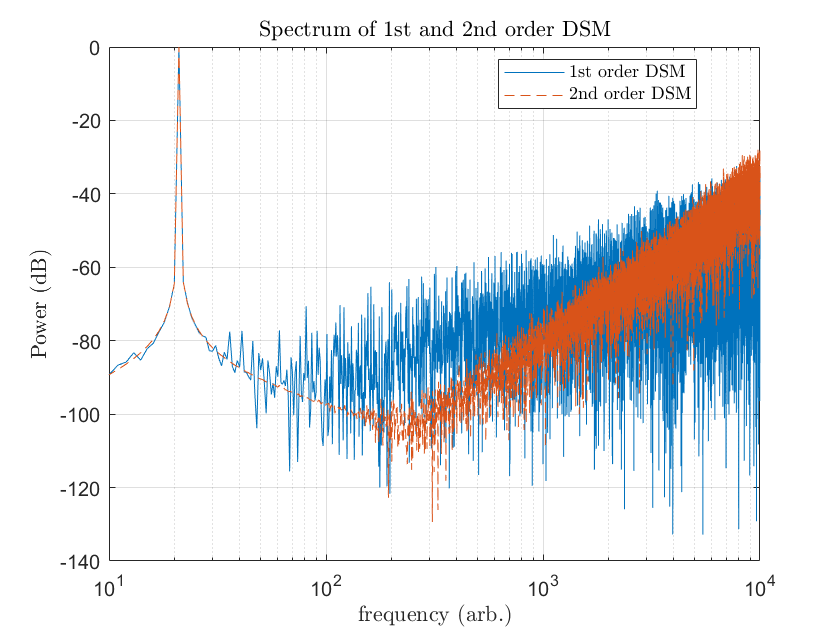
Looking at the spectrum, one can easily see that the quantization noise slope is much steeper for higher order delta-sigma modulations and thus can yield better signal fidelity at lower frequencies. The low frequency peak's "skirt" is due to finite sampling. The signal is actually just a delta-peak in frequency space and has no skirt (other than some vanishingly small one related to the phase noise of the digital clock, but that's another story and not relevant for this context). 
DSM is of course not limited to just 1-bit, but one can use it to improve the SNR of n-bit converters as well if they are capable of operating fast enough relatively to the signal of interest. The image is from 4-bit converter modulated by 2nd order DSM.


The effect of higher order DSMs on quantization noise.

Below, 1-bit 1st order DSM and 4-bit 2nd order DSM demonstration code in Matlab.

out = 0;
int = 0;
for x = 1:length(t)
    int = int + sin(pi*t(x)) - out(x);
    if int > 0
        out(x+1) = 1;
    else
        out(x+1) = -1;
    end
end

%%

out2 = 0;
int1 = 0;
int2 = 0;
for x = 1:length(t)
    int1 = int1 + 6*sin(pi*t(x)) - out2(x);
    int2 = int2 + int1 - out2(x);
    out2(x+1) = round(int2);
end

Saturday 1 August 2020

EGA to PVM

I bought an EGA display card for ISA recently. EGA games run without scan doubling so they looked a bit different originally on real EGA monitor when compared to VGA monitor and I hadn't actually ever seen this so I figured I'd try. Unfortunately I don't have an EGA monitor or CGA monitor (low resolution EGA is compatible with CGA-monitors) and they are quite difficult to come by. EGA as well as CGA uses digital TTL signals instead of analog RGB like VGA monitors. VGA monitors are also incompatible with CGA and EGA timings so I would have to figure something out.


I do have a PVM capable of displaying NTSC signals (basically a TV), including RGB input and since most EGA games are running in the low resolution mode with NTSC compatible timing, I figured it might be relatively easy to botch something up. PVM only accepts CSYNC so I would have to convert VSYNC and HSYNC. Unfortunately they need to be inverted so I had to use an active logic circuit for that instead of just something passive. Luckily the logic is quite simple. Another thing is that TTL levels are too high for PVM, but simply placing 1 kohm resistor in series divides the voltage down sufficiently (into 75 ohm input). Maybe this division is even a bit too much, but it's what I had at hand. Below is the schematic I used.


Unfortunately the CGA/EGA color brown is handled in a "nonlinear" fashing and would require a bit more logic to display it correctly. Here it instead of being brown looks more yellow. However, the other 15 colors are fine.


This is how it would look with the correct shade of brown.


My botched board is maybe a bit nasty, but it works fine.


Monday 20 July 2020

FPGA to ISA-bus

I bought a while ago a few of the cheap FPGA boards from ebay for 10 € a pcs and decided to test whether one could interface the old ISA bus with it. One issue is that this FPGA board is not 5 V tolerant so I decided to try with 10 kohm resistors in series with the pins and this seemed to be all that was needed or at least so far everything seems ok for standard port writes even if I'm not entirely sure if this is safe in the long run.


I ordered some rather blank ISA boards from JLCPCB for 2 € for 5 boards and soldered some tests leads to 8 data pins and 10 address pins.


The 8 data pins are located at A9-A2 and the 20 address pins are located at A31-A12. Additionally we need nIOW for I/O write which is located at B13 and GND that is located at B1.


This is how the thing looked like. I suppose one could have powered the FPGA board directly from the ISA slot, assuming it can supply enough current. That way one could make a rather standalone board, but so far I didn't try this. Actually, in this picture I have only 9 address pins connected, but it would be more standard to use 10 address pins.


I wrote a quick VERILOG to control the FPGA board LEDs. Basically all this does is set the LEDs to match the data bits when I/O write occurs and the address is 511.

module C2(LED, ADDR, DATA, nIOW);

output  [2:0] LED;
input   [8:0] ADRR;
input   [7:0] DATA;
input         nIOW;

reg     [2:0] leds;
assign LED = leds;

always @(negedge nIOW)
begin
if(ADDR == 511)
leds <= DATA;
end

endmodule

I also wrote a quick PASCAL program to test with a binary counter.

var
  a, b : byte;
  c : word;
begin
  for b := 0 to 4 do
    for a := 0 to 7 do
      for c := 0 to 32768 do ;
      for c := 0 to 32768 do port[511] := a;
    end;
  end;
end.

All seemed to work well on the first try so it appears making a rudimentary ISA device is very easy.

[http://www.hardwarebook.info/ISA]

Sunday 14 June 2020

Phosphorescence decay of LIT

I bought this phosphorescent material already a while ago, because I was fascinated by the long decay time compared to most other materials. One could faintly see the glow even after a week from just 1 second of illumination by a 1 W 445 nm laser. Even moderately higher temperature like touch by a human hand also seemed to expedite the release of the stored energy in this material significantly and this effect was clearly visible even hours after the first excitation. After long period in the dark and drained from stored energy, application of heat did not cause emissions as expected.

The seller claims it can be excited by heat, but this is of course nonsense. In general only wavelengths shorter than the emission spectrum can excite so infrared and heat can only expedite the release of the already stored energy, but not cause excitations. Excitation by heat under equilibrium condition is forbidden by the laws of thermodynamics.

It it is still true that under nonequilibrium conditions such as high intensity infrared irradiation can a process called frequency upconversion occur, but these are very rare events, do not apply to this case and do not come into conflict with the laws of thermodynamics.


I made a quick detector from a photomultiplier tube and a metal can and the proceeded to log the tube output using a raspberry pi and a digital multimeter.


It seems this material doesn't exhibit typical exponential decay one would normally expect, but rather it seems to decay first at a faster rate and then slow down. The measurements below indicate that the intensity will drop to approximately 1:10 of the initial intensity during the first hour, but will take something like 18 hours to drop to 1:100. Human eye adjusted to dark can still detect the output probably even if it's only 1:1000 of the initial. I don't know what exactly is the cause of this non-exponential behavior in this material, but I suspect there is some kind of statistical mix of different decay times at play here. Unfortunately I couldn't find my strontium aluminate right now for comparision. I guess some events are fast, some are slow and these then together will lead to this decay curve. I know I'm far from the dark counts of the tube and it's not saturating either so all should be good. The quantitative results also seem to match the qualitative results as far as my eye can tell so this really is the way this material behaves. Thiugh, after long enough it seems to settle to exponential decay so perhaps the assumption is correct. Perhaps I should also check how the emission spectrum looks like, but for that I'll have to wait for my spectrometer to arrive.


This is the same detector which can count individual photons. Although, the quantum efficiency is only slightly above 20%.


...got my spectrometer now and measured a bunch of things...


Monitor red doesn't appear to be very natural. Because I excited quinine with 404 nm laser, the peak is seen in the fluorescence spectrum as well as fluorescence (fluorescence lifetime is so short that afterglow can't be measured directly this way). LIT phosphorescence spectrum doesn't show the 445 nm excitation as the excitation is off when collecting the spectrum as phosphorescence afterglow decays slow enough. My 445 nm laser seems to be frequency upconverted from IR and the IR peak is visible as well (barely at the edge of the range for my spectrometer).

Spectrum lines of my monitor displaying all white image

Sunday 12 January 2020

Sync issues solved...

No more dropped frames, the solution was...
1) LPT2MIDI allows lower delay (only times 4 in al, dx) as opposed to SBMIDI.
2) The timer is reset every 69th frame.
3) OPL3 delay (1+3 times in al, dx) is used.


I released the sources...
1) https://github.com/eigenco/LPT2MIDI
2) https://github.com/eigenco/supaplex